


Severe storms and unstable power grids often leave families in the dark, making backup electricity an urgent priority for running refrigerators, well pumps, and furnace blowers. Learning how to wire portable generator to house requires understanding safe utility isolation, proper electrical distribution, and heavy-duty cabling rather than taking dangerous shortcuts. Establishing a reliable connection protects your household appliances from voltage drops while keeping utility line workers safe from dangerous electrical backfeeding. Many property owners invest in storm-ready backup generators to supply essential split-phase power during prolonged grid failures.
A secure installation pairs an outdoor generator with an external power inlet box, a heavy-duty four-prong extension cord, and a code-compliant transfer switch or mechanical interlock kit. Understanding how to wire portable generator to house connections correctly also means addressing critical factors like cable wire gauge, neutral-ground bonding configurations, and inductive motor startup surges. Taking a systematic approach ensures your emergency power system delivers clean, dependable energy without risking electrical panel damage or carbon monoxide infiltration.


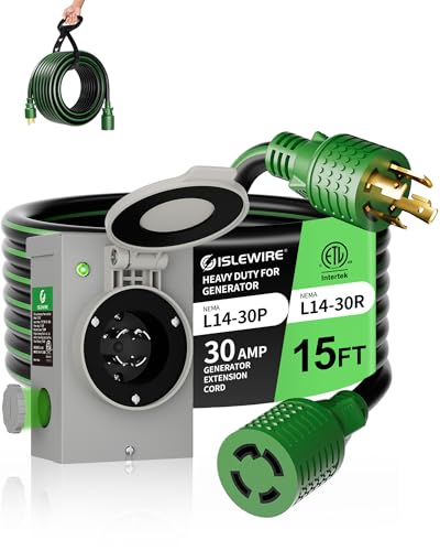
Pros
- Complete package includes both the 15-foot 10 AWG cord and outdoor inlet box
- ETL-listed construction with 100% pure copper conductors and flame-retardant PVC
- Green LED power indicator provides quick visual confirmation in dark outage conditions
- NEMA L14-30 twist-lock mechanism prevents plugs from shaking loose under load
Cons
- Fixed 15-foot cord length requires placing the generator relatively close to the house
- Requires professional premises wiring into a manual transfer switch or interlock panel
- Limited to 30-amp / 7,500-watt capacity and cannot support 50-amp generator systems
The islewire 30 Amp Generator Cord and Power Inlet Box Kit is an all-in-one electrical hookup solution engineered to connect a portable generator to a residential transfer switch or interlock panel. Positioned in the generator connection and power distribution category, this package includes a 15-foot, 10 AWG four-conductor cord and a heavy-duty exterior inlet box. For American homeowners preparing for severe storms, winter freezes, or hurricane outages, this kit eliminates the safety hazards of feeding multiple extension cords through cracked windows or propped-open doors by establishing a permanent, code-compliant outdoor entry point.
In terms of electrical capacity, the islewire system supports up to 30 amps and 7,500 watts at 125V/250V split-phase power. The 15-foot power cable is built with four 10 AWG pure copper conductors wrapped in a durable, flame-retardant PVC jacket, matching standard 30-amp portable generator output specifications. The cable features standard NEMA L14-30P male and NEMA L14-30R female twist-lock plugs. When paired with a generator producing running watts within the 7,500-watt threshold, this connection delivers dual-voltage 120V and 240V current to feed critical household loads like well pumps, refrigerators, furnace fans, and lighting circuits through appropriate transfer equipment.
Build quality emphasizes weather resistance and mechanical reliability for outdoor deployment. Both the heavy-duty power cord and the exterior inlet box carry ETL listings for electrical safety compliance. The inlet box is fabricated from powder-coated galvanized steel designed to endure harsh outdoor exposure including rain, snow, and high ambient temperatures. It incorporates a spring-loaded flip-top cover that seals the receptacle against moisture and debris when disconnected. A built-in green LED indicator glows when the generator sends active voltage, allowing quick visual confirmation from a distance during nighttime power failures. Inside the enclosure, pre-drilled knockouts simplify conduit attachment for clean wall mounting.
Practical usability and storage are supported by thoughtful accessories. The kit includes a heavy-duty cord organizer strap and a zippered storage bag, protecting the 10-gauge cable from physical damage, sunlight degradation, and tangling when stored in a basement, garage, or RV compartment. The twist-lock interface requires only a firm push and a clockwise quarter-turn to lock securely into the inlet box and generator receptacle, ensuring that normal engine vibrations will not work the connectors loose during extended runtimes.
While this kit provides solid utility for standard 30-amp setups, buyers must consider several realistic limitations. The 15-foot cord length restricts generator placement, requiring careful site planning to keep the generator exhaust pointed safely away from residential windows, doors, and fresh-air intakes. Furthermore, the 30-amp, 7,500-watt maximum capacity will not support large 50-amp generators or heavy whole-house electrical loads like large central air conditioners and electric water heaters. The outdoor inlet box also requires direct wiring into a UL-listed manual transfer switch or mechanical panel interlock kit, which necessitates proper electrical knowledge or professional installation by a licensed electrician.
The islewire 30-amp hookup kit is an excellent, budget-conscious choice for homeowners, rural property owners, and emergency-preparedness planners who own a portable generator with a 120V/240V L14-30R outlet. It establishes a secure, durable link between your backup power source and home electrical system. However, households with high-capacity generators delivering 9,000 running watts or higher should bypass 30-amp assemblies and choose a 50-amp NEMA 14-50 or CS6365 power inlet setup to prevent electrical bottlenecks.
The islewire power inlet box utilizes a four-wire configuration consisting of two hot legs, one neutral, and one equipment ground. This setup accommodates 120V/240V split-phase systems standard in North American residential wiring, allowing balanced distribution across panel busbars.
This inlet box must always connect to an approved manual transfer switch or an electrical panel fitted with a mechanical interlock kit. Homeowners must never attempt dangerous backfeeding by wiring an inlet directly to an unprotected household breaker, as backfeeding risks sending lethal voltage onto utility lines and endangering utility lineworkers.
The pre-drilled knockouts on the galvanized steel box accommodate standard conduit fittings, simplifying the path through exterior siding into your basement or garage electrical panel. Professional installation by a licensed electrician is recommended to comply with local building codes and National Electrical Code standards.
Any fuel-burning portable generator produces dangerous carbon monoxide gas and must remain strictly outdoors in an open, well-ventilated area. Never run a generator inside a garage, shed, carport, or near open windows, even if the generator features an automatic CO shutoff sensor.
Because the included power cord measures 15 feet in length, verify that your designated outdoor generator operating location provides adequate clearance from exterior wall openings before installation. The generator exhaust must direct away from the home to prevent toxic fumes from drifting inside.
The inlet box features a spring-loaded flip cover that keeps rain and snow away from the contacts during idle periods. When connected, the weather-resistant twist-lock interface maintains a water-tight seal against typical rain and outdoor elements, though the generator itself should remain sheltered under an approved weatherproof running cover.


Safe and Code-Compliant Methods for Connecting a Portable Generator to Your Home Panel
Connecting a generator directly to your home electrical system requires strict adherence to safety standards, electrical codes, and proper mechanical hardware. Attempting to power a house through makeshift cords introduces severe hazards, including electrical fires, equipment burnout, and lethal electrocution risks for utility line technicians. A code-compliant installation creates a fully isolated pathway that channels electricity safely from the generator into your circuit breaker panel. Understanding the components, cabling standards, and procedural rules ensures your household retains dependable power during severe weather blackouts.
The Critical Danger of Backfeeding and Why Electrical Code Demands Utility Isolation
Direct backfeeding occurs when someone attempts to connect a running generator into a household appliance outlet using a hazardous male-to-male cord. This practice is extremely dangerous, illegal in most jurisdictions, and completely prohibited by the National Electrical Code. When power enters the breaker panel without utility isolation, electricity travels backward through your service entrance cables and into the neighborhood utility transformer. That transformer immediately steps the voltage back up to thousands of volts, sending lethal high-voltage surges down power lines where repair crews are actively working.
Backfeeding also compromises the safety of your own living space by bypassing essential panel overcurrent protection devices. A standard wall outlet is never designed to function as an electrical source, meaning circuit breakers cannot reliably protect against severe overloads or short circuits. If utility power unexpectedly restores while a backfed generator is running, the colliding electrical out-of-phase waveforms will instantly destroy the generator alternator and can trigger catastrophic electrical fires. Installing an approved mechanical disconnect eliminates these risks by ensuring your home draws power from either the grid or the generator, never both simultaneously.
Choosing Between a Manual Transfer Switch and a Breaker Interlock Kit
Homeowners generally choose between two approved hardware configurations to isolate utility power: a dedicated manual transfer switch or a mechanical breaker interlock kit. A manual transfer switch functions as a secondary subpanel wired directly adjacent to your main breaker box. This switch contains dedicated toggle switches that control individual critical circuits, such as your heating system, refrigerator, well pump, and lighting branches. Transfer switches offer straightforward operation because you simply flip individual switches between line power and generator power, eliminating any possibility of human operational error.
A mechanical panel interlock kit provides a more flexible, cost-effective alternative for whole-panel power management. The interlock consists of a precision-engineered metal plate installed directly onto the face of your main electrical panel. This mechanical plate physically slides back and forth, preventing the generator backfeed breaker from switching on unless the main utility service breaker is completely shut off. Because an interlock feeds power directly into the main panel bus bars, you can energize virtually any branch circuit in your home as long as the total electrical demand remains within your generator output capacity.
Selecting the Right Power Inlet Box and Outdoor Cord Set
A dedicated power inlet box serves as the external electrical bridge mounted securely to the exterior wall of your home. Unlike standard female receptacles, a power inlet box houses male prongs protected inside a heavy-duty, weatherproof enclosure. Premium inlet boxes feature durable powder-coated steel or aluminum housings, spring-loaded flip covers to repel driving rain, and integrated LED power status indicators that illuminate when generator voltage reaches the box. Hardwired electrical conduit connects this inlet box directly through the wall into your transfer switch or interlock breaker.
Selecting the correct cord set depends entirely on the rated wattage and amperage of your generator outlet panel. A 30-amp generator setup uses a four-prong NEMA L14-30 twist-lock connection wired with 10 AWG copper conductors capable of handling up to 7,500 continuous running watts. Twist-lock connectors ensure the heavy cable remains securely seated in the receptacle despite engine vibrations, high winds, or heavy snowfall. Heavy-duty 30-amp cord sets feature rugged, flame-retardant thermoplastic jackets that resist cold cracking, oil exposure, and abrasive surface wear during harsh outdoor emergency conditions.
Larger home backup generators delivering over 7,500 running watts require a 50-amp connection to distribute full split-phase electrical capacity safely. A 50-amp setup typically utilizes a NEMA 14-50P plug paired with a specialized CS6364 or SS2-50R twist-lock connector. These heavy-duty cords incorporate 6 AWG conductors for the hot and neutral lines alongside an 8 AWG ground conductor to handle loads up to 12,500 watts without dangerous overheating. Using an undersized extension cord causes significant voltage drops over long distances, which can overheat the electrical wire insulation and potentially damage sensitive electronic appliances inside your house.
Sizing Electrical Loads and Managing Motor Startup Inrush
Sizing your generator correctly requires distinguishing between continuous running wattage and peak starting surge wattage. Resistive electrical loads, such as incandescent light bulbs, electric space heaters, and baseboard elements, draw a constant amount of electrical wattage from the moment they are turned on. Inductive loads that contain electric motors, including sump pumps, deep-well water pumps, and refrigerator compressors, require a massive surge of current known as Locked Rotor Amps to get moving. This startup inrush demand can briefly consume two to three times the equipment rated continuous running wattage.
Attempting to start large motor-driven appliances simultaneously will quickly overwhelm an undersized generator, tripping its circuit breakers or stalling the engine. When sizing portable generators for central cooling loads or water pumps, homeowners must calculate the maximum cumulative surge wattage before configuring their emergency circuits. Staggering the startup sequence helps manage this demand effectively. By starting the heaviest motor loads first and allowing their operating current to stabilize before turning on auxiliary branch circuits, you maintain stable system voltage and prevent unwanted engine bogging.
Split-phase generator systems deliver both 120-volt and 240-volt power across two separate 120-volt hot legs, commonly labeled Leg A and Leg B. Pure 240-volt appliances, such as well pumps or electric water heaters, draw power equally from both legs simultaneously. Standard 120-volt household branch circuits draw power from only one leg at a time. If you inadvertently assign too many high-draw 120-volt appliances to circuits running on Leg A, that single alternator winding can become heavily overloaded while Leg B remains virtually idle, causing severe voltage instability and premature alternator wear.
Navigating Neutral-Ground Bonding for Residential Transfer Switches
Proper neutral-ground bonding configuration represents one of the most misunderstood aspects of wiring a generator to a house panel. The National Electrical Code mandates that an electrical system must have exactly one single point where the neutral conductor bonds to the grounding electrode system. In standard residential wiring, this primary bond occurs exclusively inside your main service entrance panel. When you connect a portable generator to a standard transfer switch or interlock kit, the neutral line remains continuously connected to the household utility panel ground.
If your generator alternator features a bonded neutral, where the neutral conductor connects directly to the generator frame, connecting it to a bonded house panel creates a dangerous dual-bond condition. This dual bond creates parallel return paths for electrical current, causing small amounts of current to travel across equipment grounding conductors. Furthermore, modern portable generators equipped with onboard Ground Fault Circuit Interrupter breakers will immediately trip upon sensing this secondary ground path. For standard home backup through an unswitched neutral transfer switch, operating a generator with a floating neutral configuration ensures full electrical code compliance and prevents nuisance breaker tripping.
Outdoor Placement, Exhaust Clearance, and Weather Protection
Operating an internal combustion generator requires strict adherence to outdoor setback guidelines to eliminate the lethal risk of carbon monoxide poisoning. Combustion engines produce vast amounts of colorless, odorless carbon monoxide gas that can penetrate living quarters through minute cracks, soffit vents, and window seals. Safety standards require placing running generators a minimum of 20 feet away from any occupied structure, including garages, carports, and breezeways. The engine exhaust port must always face away from nearby doors, operable windows, and fresh air intake vents.
Running a generator inside an attached garage, even with doors and windows completely open, is extraordinarily hazardous and can lead to fatal carbon monoxide accumulation within minutes. Many modern units integrate automatic carbon monoxide shutoff sensors complying with standards like UL 2201 or PGMA G300. However, these electronic safety devices are intended as emergency fail-safes rather than excuses for poor machine placement. When outdoor space is limited or quiet operation is paramount for delicate medical equipment like CPAP machines, homeowners often turn to zero-emission battery backup power systems that can be operated completely indoors without any exhaust danger.
Inclement weather often accompanies major electrical outages, requiring practical strategies to shield running generators from driving rain, freezing sleet, and drifting snow. Moisture entering electrical receptacles or alternator vents can cause direct short circuits and severe ground faults. Never cover a running machine with makeshift tarps, plastic sheeting, or plywood boxes that restrict airflow or trap engine exhaust heat. Purpose-built, fire-retardant generator running covers maintain structural airflow while shedding precipitation safely, allowing the machine to cool its engine block while keeping electrical outlets dry.
Step-by-Step Connection and Startup Sequencing Protocol
Establishing a dependable startup sequence ensures smooth operation and prevents dangerous electrical surges when connecting your backup system. Begin by positioning your generator on level, dry ground at least 20 feet away from your home, verifying proper engine oil levels and fresh fuel supplies. Inspect your four-prong power cable for any cracked insulation, bent contact pins, or signs of overheating before attaching the female twist-lock connector to your outdoor inlet box. Plug the male connector securely into the matching generator 120/240-volt receptacle, twisting the locking collar firmly into place to seal out moisture.
Before cranking the generator engine, verify that the main output circuit breaker on the generator control panel is switched to the off position. Start the engine according to the manufacturer procedure, whether using an electric push-button start, wireless remote, or manual recoil pull rope. Allow the small engine to idle smoothly for two to three minutes so the internal oil warms and the electronic governor stabilizes engine RPM at 3,600 revolutions per minute. Once the motor runs smoothly and voltage output settles, switch the generator control panel breaker to the on position.
Move indoors to your electrical panel to initiate power transfer from the utility grid to the generator source. If using a manual interlock, shut off all individual branch breakers, switch the large main utility breaker off, slide the mechanical plate upward, and switch the generator backfeed breaker on. Turn on your primary inductive circuits one by one, starting with your refrigerator, well pump, or sump pump, allowing each motor to complete its startup cycle before proceeding. Once your heavy appliances run steadily, selectively energize low-draw lighting circuits, internet routers, and essential wall outlets without exceeding your continuous running wattage capacity.
Post-Outage Shutdown and Grid Power Restoration
When municipal utility power restores, returning your household to the main grid requires a careful, reverse sequencing protocol. Start at your breaker panel by shutting off individual branch breakers or flipping the transfer switch toggles back to the utility position. In an interlock setup, switch off the generator backfeed breaker, slide the safety plate back down, and firmly engage the main utility service breaker. Once your household runs on grid electricity, allow your generator engine to run completely unloaded for several minutes so cooling air dissipates residual heat from the alternator windings and cylinder head.
Switch off the generator engine, turn the fuel shutoff valve to the closed position, and let the exhaust muffler cool completely before handling electrical cords. Disconnect the power cord from both the wall inlet box and the generator, coiling it loosely to prevent internal wire strand fatigue. If the generator will remain idle for several months, running the carburetor float bowl completely dry or adding a quality fuel stabilizer prevents stale ethanol gasoline from gumming internal jets. Storing your machine with clean oil, a fresh fuel system, and a trickle-charged starter battery ensures dependable performance whenever the next unexpected power outage strikes.
Practical Verification and Long-Term Maintenance Takeaways
Maintaining a dependable residential generator setup requires regular operational verification and preventative maintenance routines. Performing brief test runs every two to three months under real electrical loads verifies that the governor, voltage regulator, and manual transfer switches function correctly under pressure. During these exercise sessions, checking output voltage and line frequency with a digital multimeter confirms the generator delivers a stable 120/240 volts at exactly 60 Hertz. Periodically inspecting your outdoor inlet box, receptacle gaskets, and cabling for signs of corrosion or pest intrusion ensures your emergency power infrastructure remains completely storm-ready year after year.
Engaging a qualified licensed electrician to install your power inlet box and transfer equipment guarantees full compliance with local municipal codes and utility safety regulations. A professional installation verifies wire ampacity ratings, ensures accurate split-phase branch circuit balancing, and properly tests grounding rods against ground fault hazards. Keeping an emergency load management chart mounted near your breaker panel reminds household members which high-draw appliances can run simultaneously. With the proper hardware, disciplined operational sequencing, and routine equipment upkeep, your portable power setup provides reliable home security through any blackout.



Write Your Review
No reviews yet. Be the first to share your experience!